Half full bridge rectifier calculator full#
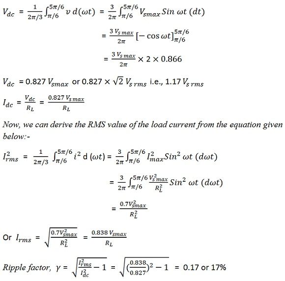
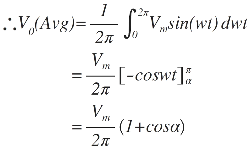
Thus ripple factor, γ = √(1.11 2 – 1) = 0.482 Regulation of Full Wave Rectifier Rectified output voltage, form factor is given as: =0.812(1+R f / R Load) Ripple Factor of Full Wave Rectifier I 2 RMSR f + I 2 RMSR Load = (I 2 m/2) (R f + R Load) Now the amount of power delivered to the loadĪlternating (AC) power input to the transformer = power dissipated at the diode + power dissipated from load resistance RL I RMS = Imax / √2 Rectification Efficiency of Full Wave Rectifier Vdc = I dc RL = 2/ (Π I maxR L) Root Mean Square (RMS) Value of CurrentĮffective or RMS value of the current flowing through the load resistance RL can be given as: The magnitude of the direct current Idc is equal to the average value of the ac current and is obtained by integrating the current I1 between 0 & Π or current I2 between Π & 2Π.ĭC or average value of voltage across the load is given by The current through the load RL is the sum of the two halves of the ac cycles. I max = V smax/(2R F + R L) Output Current of Full Wave Rectifier The peak value of load current flowing through the load resistance R L is :

I = I 1 + I 2 = I max Sin wt for complete cycle The sum of currents I 1 and I 2 flows through the load resistance R L which is given as: I1 = 0 and I 2 = I max Sin wt for the second half-cycle.I1 = I max Sin wt and I 2 = 0 for first half-cycle and.

Let us suppose that the diode has a forward resistance of R f ohms and the reverse resistance equals to infinity, hence current through the R L load can be given as : The value of the instantaneous applied voltage to the rectifier is given as Thus in the bridge rectifier circuit, two diodes out of four conduct during one half-cycle and henceforward resistance becomes double that is 2RF. Maximum of secondary Voltage = Peak Inverse Voltage (PIV) of the bridge rectifier The waveform of the rectified input will look like Hence negative cycle is rectified as it appears across the load. So no current flows through the path 1-2 and 3-4. The other two, i.e., D1 & D4 are reversed biased for this cycle. Thus diodes D2 & D3 are forward biased and the currents follow the path as 3-2-4-1. in the next cycle, the upper portion of the transformer becomes negative when compared with the lower portion of the same. Thus, no current flows through the path 2-3 and 1-4.ĭuring the negative half-cycle, i.e. Similarly, diodes D2 and D3 are reverse biased. The currents follow the path 1-2 and enter the load. Thus during the first half diodes, D4 and D1 are in forward biased. Now when the AC input is given, during the first half cycle, the upper part of the transformer becomes positive when compared to the lower half of the same. The load R load is connected to the remaining two points of the bridge. Whereas, the secondary of the transformer is diametrically connected to the two diametrically opposite points. The primary winding of the transformer is supplied with a sinusoidal supply.

The working of the full-wave rectifier is simple. All the four diodes are connected in the form of a diamond-shape to the transformer and the load as in the shown circuit diagram.

Four diodes are used in the bridge rectifier.


 0 kommentar(er)
